The principles of schematic design for CO2 systems

CO2 (also known as R744) is a highly efficient, non-corrosive and non-toxic natural refrigerant.
This makes it an excellent choice for heat pump systems. Which is why we’ve been at the front of the curve, designing, manufacturing and installing CO2 heat pump systems for years here at Clade!
Here, I’ll walk you through the principles of schematic design for CO2 heat pump systems and introduce you to the main considerations that need to be taken into account when designing a system that contains this refrigerant.
But first…
What is a schematic design?
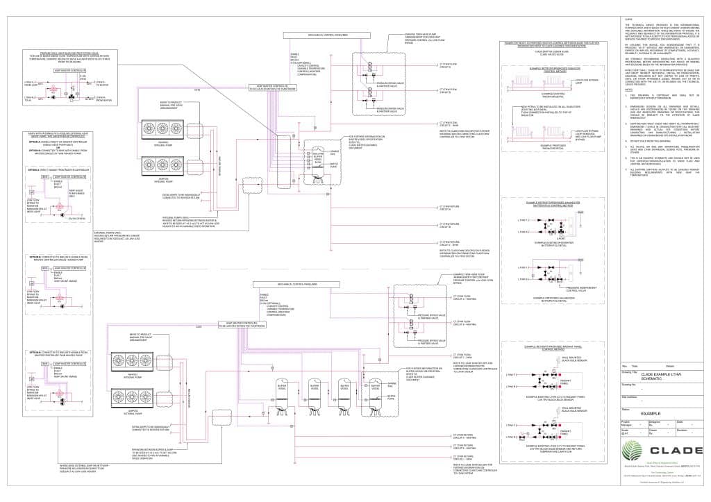
In simple terms, a schematic is a blueprint of the fluid system.
It’s essentially a full drawing of how all the pipework in a building connects, showing the entire building on one piece of paper. This includes all emitters, heat pump units, buffer vessels, valves and more.
By starting with a schematic, we’re able to figure out how the fluid system in a building will work and be controlled, which is a vital part of the design process.
Achieving a 30C return
With CO2 heat pump systems, we design for a 30C return temperature.
By return temperature, we’re referring to the temperature at which water returns to your heat pump after circulating through the heating system.
Why design for a 30C return?
30C is the optimal return temperature for maximising a CO2 heat pump’s efficiency (leading to lower energy consumption and reduced operational costs).
This is essentially due to the refrigerant’s unique properties – and the fact that we need a return temperature that’s within the envelope operating temperature of CO2 to get out of the transcritical state that’s been achieved using compression from the compressor.
30C is also well below our maximum current return temperature for CO2, which is 38C.
This gives our systems some wiggle room before the return temperature reaches a figure that would cause the heat pump to turn off.
How do we achieve a 30C return?
Achieving a 30C return is all about emitter design and controls.
A schematic shows all your valves and how these are controlled – for instance via a Building Management System (BMS) or master controller system.
Below are diagrams of the emitters that the industry uses 95% of the time:
- Radiators
- Air handling unit coils, heater batteries or fan coil units
- Radiant panels
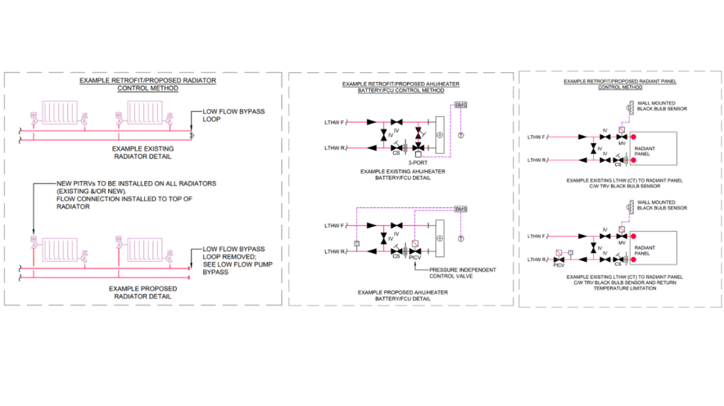
These diagrams essentially show that, to achieve a 30C return, all you need to do is have two-port constant temperature variable volume control, and then also, as a backup, look at the return temperature coming off the emitter.
In other words, you control the flow rate through the emitter on your off temperature (meaning the room’s temperature set point). Then, at the same time, you monitor the return temperature coming off the emitter and limit this so that it doesn’t go beyond the accepted range of the CO2 air source heat pump system.
You can get much more detail on the role of control valves and emitter design over on our dedicated blogs.
The importance of control
Taking proper control of emitters isn’t a new concept.
Two-port control is a part of standard building services, and we’ve been doing it for decades here at Clade.
Perhaps more importantly, all heating systems can benefit from it and should be using it. Even with a boiler, achieving the right return temperature will optimise its efficiency.
So, why are many contractors uninformed and inexperienced in this area?
Well, the return temperature doesn’t make quite as big of a difference in boilers as it does in natural refrigerant heat pumps. So, contractors have historically gotten away without putting these control valves in, which is cheaper.
However, it’s not rocket science.
Two-port control is simply about slowing the flow rate down. Yes, it’s more expensive than going without. But it’s absolutely worth it to achieve better operation control and efficiencies on any system – boilers, CO2 heat pumps and propane heat pumps alike.
Achieving separation between primary and secondary
Heating systems all have a primary side and a secondary side.
The primary side is your heat generation. So, for instance, you could have an air source heat pump or a boiler doing your primary loop.
Meanwhile, the secondary side is the loop that goes out to the emitters in your building and back.
These two loops need to be separated in some way.
On boiler systems, this can be achieved using a low loss header, which is essentially a really big pipe. Your boiler feeds into the top of it and pulls from the bottom, while your system side pulls from the top and feeds back into the bottom.
When it comes to air source heat pumps, we use the same philosophy. But instead of a big pipe, we use a buffer vessel.
The air source heat pump flows into the top of the buffer vessel and pulls from the bottom, while the secondary side pulls heat from the top and puts the cold return fluid into the bottom.
In this way, the buffer acts as the hydraulic separation between the primary side and secondary side and allows both to do their jobs without interfering with one another.
Dealing with domestic hot water production (DHW)
One of the myths that you might hear about heat pumps is that they’re not reliable at domestic hot water production (DHW).
However, this is simply not true!
At Clade, our CO2 heat pumps have proven repeatedly that they can consistently produce a hot water supply – both at 60C, and even up to 80C.
So, how do we achieve this while maintaining a low 30C return temperature? Here are the key considerations.
1. The ‘on’ temperature
Firstly, the ‘on’ temperature of the water that you’re raising has to be lower than the 30C low temperature hot water return off the primary side of the plate heat exchanger.
So, as an example, if the temperature going on to a plate exchanger is 10C, this can easily be raised to 60C using a 70-30 system.
On the other hand, if the temperature in your DHW cylinder happened to be 50C, you wouldn’t be able to raise this to 60C using a 70-30 system. This is because, on the low temperature hot water primary side return, you’d be coming off at 55C (which is higher than 30C).
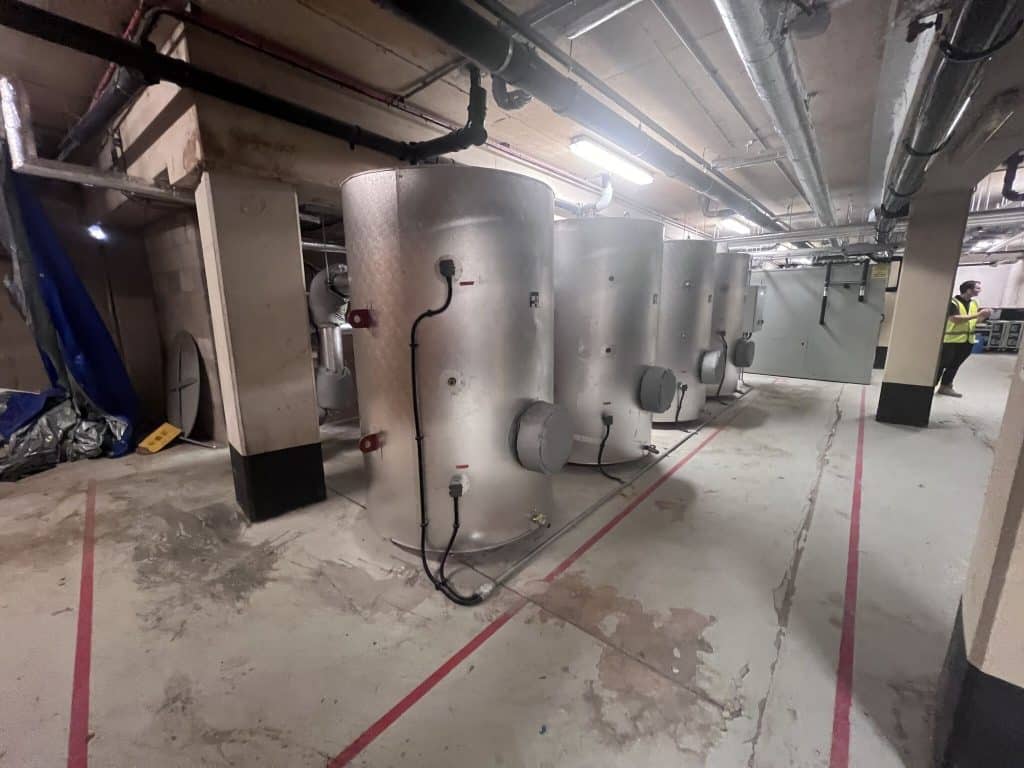
2. Domestic hot water cylinders
When it comes to DHW, we have two cylinders.
One is maintained hot at all times (the hot store vessel), using direct electrical immersions to cover your domestic or water return losses.
The other is known as your stratification cylinder.
When people turn on the taps in your building, the cold return water gets fed into the bottom of this stratification cylinder, which is separated into layers based on temperature (known as stratification).
At the same time, the hot water at the top of the cylinder (which has reached the desired temperature) gets fed into the bottom of the first hot store vessel, ready to go when someone turns a tap back on.
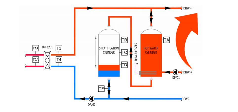
3. Stratification control
The way that we raise that 10C ‘on’ temperature with CO2 is through stratification control.
Essentially, when cold return water first enters the bottom of the stratification cylinder, there’s a point where you’ll have 60C (or your desired temperature) at the top of the vessel and 10C at the bottom.
However, as taps stay on, cold water will continue to come in at the bottom, while hot water will continue to go out of the top.
So, the stratification layer will slowly move up the vessel, and you’ll eventually end up with the whole cylinder at 10C (while your hot store vessel is still fully hot).
At this point, it’s time to turn on your DHW production and use your plate heat exchanger to raise the temperature of the cylinder from 10C to your desired temperature.
In this way, it’s possible to maintain that 70-30 flow/return on the primary side.
We have a Clade domestic hot water controller available which will monitor and control all the DHW stratification control requirements.
This controller also goes through a destratification programme once an evening as a minimum to maintain all cylinders above 60C for 1 hour in 24.
What happens when my return temperature goes up?
If your return temperature climbs above a certain figure (38C for Clade CO2 heat pumps), your air source heat pump will turn off.
So, it’s important to have a building management system (BMS) in place that will monitor your emitters and flag a rise in return temperatures.
Raised return temperatures can happen for two reasons:
- You haven’t got proper control of a secondary system
- Faulty equipment (eg. a faulty valve, faulty cable, or faulty fan in an air handling unit)
A BMS won’t just flag high return temperatures. It can also tell you which part of the system is causing the problem (whether it’s an emitter, fan coil or air handling unit) so that you can easily carry out some maintenance to correct the issue.
Better still, you can programme a BMS with high-level limits and alarms so that, if return temperatures do start climbing, you can hopefully resolve the issue before it gets to a stage where the heat pump would turn off.
At Clade, our innovative Master Controller optimises performance across your whole heat pump system and empowers operators with clear, actionable insights. So, you can ensure that your system is extremely reliable.
Refrigerant safety
As it’s non-flammable and non-toxic, CO2 is classified as a safety group A1 refrigerant – the safest class available!
However, it does run at a very high pressure – around 120 bar. This is about 120 times greater than atmospheric pressure.
It’s what enables CO2 to go into a transcritical state (where it possesses properties of both liquid and gas) and achieve those sought-after high temperatures.
But it can also cause some people to worry about the safety implications of such a high-pressure system.
Rest assured, this isn’t something that you need to be concerned about.
Fully contained
Firstly, all Clade CO2 units are fully contained in compressor housing.
Everything inside these containers is rated at high pressures – including the equipment. And all joints are welded together to ensure they can withstand the pressure.
This means there’s no exposed pipework to worry about.
Testing
We pressure test our units using nitrogen before they get filled with CO2 gas.
Testing takes place within a special pressure test bay within the factory, which has thick, bomb-proof doors.
Every Clade unit is tested and certified before it leaves.
Burst discs
In a low-temperature hot water system, you’d set safety valves (also known as pressure relief valves) to release at around 0.6 to 0.9 bar above normal operating pressures.
The role of a safety valve is to release pressure in the system if there’s a fault and temperatures start rising, so that pipework doesn’t burst.
When it comes to CO2 systems, however, we use bursting discs as well. This is because CO2 runs at such high pressures.
Essentially, if the plate heat exchanger that sits between the refrigerant and the low-temperature hot water ever ruptures, you’ll have a sudden increase in pressure in a part of the system that isn’t rated for it.
Your bursting disc has a larger diameter than a safety valve and is designed to completely rupture if there’s a sudden pressure increase, to instantly release the high pressure.
We still use safety valves for normal fluctuations. But the addition of a bursting disc means our systems are still incredibly safe if, for whatever reason, there’s a catastrophic failure where the CO2 enters the rest of the system.
Talk to us about CO2 systems
As you can see, CO2 heat pump systems are a fantastic way of generating both space heating and DHW safely, efficiently and without harming the environment.
And creating a schematic design is an essential step in making sure your system is working for your building and its inhabitants, rather than against them.
At Clade, we have over 35 years of experience working with natural refrigerants like CO2. So, we know what we’re doing when it comes to designing, manufacturing, installing and maintaining these systems.
In fact, if you’re interested in swapping your commercial boiler for a natural refrigerant heat pump, we may just be the safest pair of hands there is!
Get in touch with our team to learn more and to start the ball rolling on your project.